
products categories

contact us
- If you have questions, please contact us, all questions will be answered
- Tel : 18030236818
- Fax : +86-592 5237901
- Email : dexing@china-dexing.com
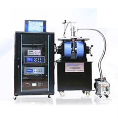
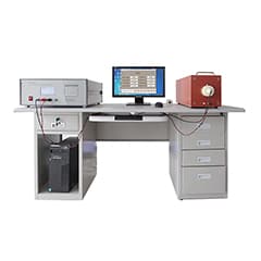

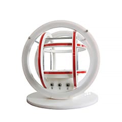
Hall Effect Measurement System
Measurement of magnetic field distribution of current carrying coil
1.experimental principle
This experiment is a confirmatory experiment, so the data measured in the experiment should be consistent with the theoretical law, which is also a way to check whether the data is correct
The magnetic induction intensity of the current-carrying circular coil gradually decreases along the axial (x) direction
The magnetic induction intensity of the current-carrying circular coil increases gradually along the radial direction (Y)
Helmholtz coil: Two coaxial coils of the same radius, number of turns, and spacing equal to the radius
The axis of the coil near Helmholtz is basically a uniform magnetic field
Some method of measuring magnetic field is induction method
The circular coil is energized, the detecting coil is placed in an alternating magnetic field, and the maximum induced electromotive force ε at the point is measured by rotating the detecting coil
The relationship between the magnetic induction intensity B at this point and the induced electromotive force ε is as follows:
2 experimental operation
(1) Connect the excitation voltage to the coil
(2) Measure the step-down voltage of the transfer switch
⑶ Through the excitation adjustment, select the appropriate coil current (millivolt meter reading on the right side), the actual measurement is the voltage at both ends of the 1Ω resistance inside the instrument
(4) Access the detection coil
The measurement transfer switch is equipped with detection
The maximum electromotive force induced by the detection coil in the magnetic field was measured
Note:
A. Adjust the current through the coil to an equal integer value to avoid a single coil through the current is too large, the maximum output voltage of the instrument can not make the Helmholtz line
The loop reaches this current
B. Select the center of a coil as the starting point. Single, composite, axial and radial measurements are taken from this point as the starting point
C. During the measurement process, observe whether the axial and radial numerical laws are consistent with the theory at any time