
products categories

contact us
- If you have questions, please contact us, all questions will be answered
- Tel : 18030236818
- Fax : +86-592 5237901
- Email : dexing@china-dexing.com
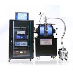
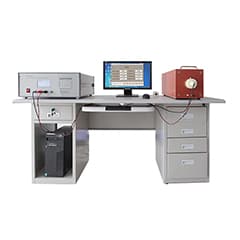
Hall Effect Measurement System
How to measure magnetic field strength and high frequency current with a magnetic field probe
The voltage signal output (UPROBE) emitted by the magnetic field probe is separated into the spectrum by the spectrum analyzer. The magnetic correction factor (Kh) is defined as: describing the relationship between the voltage signal and the relevant magnetic field (HRF). The magnetic field (HRF) is related to the current (IRF), so another correction factor is defined based on the current (IRF).

1. Magnetic field correction:
The magnetic field intensity (HRF) in the coil of the magnetic field probe can be calculated by modifying the formula of the voltage signal (Uprobe) measured from the magnetic field probe. In each individual application, the correction factor of the magnetic field probe is independent of the measurement geometry parameters, that is, the probe can be manipulated at any distance and Angle, without any correction error relative to the conductor (Fig. 2). The result is that the average magnetic field strength around the probe coil is (Fig. 1).
The magnetic field probe is located in a constant magnetic field in the full frequency range. Due to coupling factors, the voltage induced in the probe depends on the frequency. The coupling coefficient comes between the self-measured voltage (Uprobe) and the average magnetic field strength. If the correction factor is added to the measured voltage (UPROBE), the actual magnetic field strength (HRF logarithmic expression) can be obtained.
The formula can be used to determine the mean magnetic field intensity (HRF) from the measured curve (Uprobe) and correction factor (KH). The result is shown in Figure 3
2. Current correction:
There is a consistent physical correlation between the radio-frequency magnetic field (HRF) and the radio-frequency current (IRF), and the degree of their relationship depends on the geometric parameters of the current conductor layout. Therefore, the current correction factor (ki) needs to be calibrated in the test under a defined reference setting.
When the high-frequency current probe is in use, the measured current value (iCORR) will be accurately corrected only if the geometric parameters coincide with the reference Settings. If there is a deviation in the setting, the current value (ICORR) will also deviate. In this case, the calculated current value (ICORR) can only be a reference value of strength and weakness, not an accurate measurement value. During the test correction, reference Settings are made according to the following geometric parameters (Figure 4 and Figure 5) : At this time, the wire width is required to be 2mm; The height of the wire from the grounding system is 1mm; The magnetic field probe is placed on the wire (see Figure 4).
According to the current correction factor (KH), calculate the current value according to the following formula:
In this example, a constant current is used over the full frequency range (Figure 6). Through the magnetic field probe, the current into the voltage, and through the spectrum analyzer to measure the probe output voltage (UPROBE). The voltage waveform output from the probe, together with the frequency-dependent correction factor, thus measures the current in the conductor (logarithm). In this reference setting, Icorr is the current flowing through (dBuA).