
products categories

contact us
- If you have questions, please contact us, all questions will be answered
- Tel : 18030236818
- Fax : +86-592 5237901
- Email : dexing@china-dexing.com
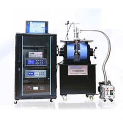
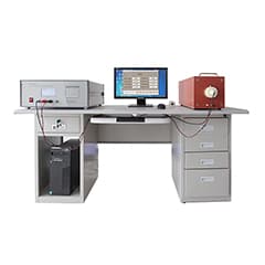
Hall Effect Measurement System
The magnetic field distribution characteristics of helmholtz coils
一、Introduction
With magnetic flux meter (table) is usually used when permanent magnet "pulling method", for the magnetization of the sample with a flat coil set of flux, this method is intuitive and effective for each different specifications of the samples, but the disadvantage is that have to do by the coil in different sizes, with very thin samples strictly, detecting coil preparation difficulty is bigger, trouble and inefficient.
Using Helmholtz coil to measure the flux can solve the above problems to a certain extent, so in recent years, domestic permanent magnet manufacturers have widely adopted this method to test batch products.
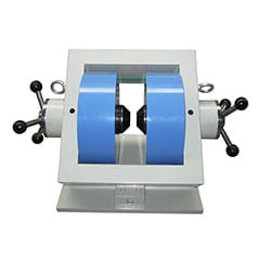
二、Characteristics of Helmholtz measuring device
Helmholtz measuring device is a cylindrical measuring device composed of two groups of coils with a certain diameter to height ratio. The sample is placed into the cylinder in the direction of magnetization or taken out of the cylinder, both of which are simple operations to achieve the measurement. According to its principle, there is no restriction on the geometrical shape of the sample to be tested, such as cylinder, disc, rectangle, tile, etc., which can be adapted (not applicable to multiple magnetic poles).
三、The use of the Helmholtz device
Helmholtz coil to adapt to a variety of size specifications of the product, so the coil frame is large, surrounded by a large area. Compared with the tight coil method, the values measured by the Helmholtz device are lower under the same turn constant. However, in the general batch measurement, its focus is to determine whether the product is qualified or not, do not pay attention to the specific value. For example, a magnetic flux of 1320 for the magnet to be measured is qualified, and 815 for the Helmholtz coil is also irrelevant, as long as the upper and lower limits of qualified products are reduced according to the new proportional requirements. However, it is worth noting that, since the accuracy of the current flux meter is about 0.5% ~ 5%, in order to play the detection accuracy of the meter, when measuring the sample with Helmholtz coil device, three or more effective numbers must be displayed, which can be changed by choosing different range and gear
四、Relationship between the outer diameter of Helmholtz coil barrel and the maximum outer diameter of the tested sample
The device can be used for testing samples with many geometrical sizes and shapes, but the maximum outer diameter has a certain limit. The general proportion relationship is as follows:
Longitudinal 70%H(H is 1/2 of Helmholtz coil height) B& J
Radial 60%D(D is the diameter of Helmholtz coil)
Longitudinal 70%H(H is 1/2 of Helmholtz coil height) B& J
五、feasibility testing
Whether any device can be used for quantitative detection, the first premise is the repeatability of the detection value, the higher the repeatability, the smaller the artificial detection error, without a certain repeatability can not be used for quantitative detection.
In the measurement of the Helmholtz coil device, the source of human error is the non-repetition of the position of the sample in the cylinder. The geometric center position of the tested sample should be as close as possible to the center position of the cylinder. The tested sample should not be close to the edge of the cylinder when placing or taking out the magnetic flux.
The radial 60%D and longitudinal 70%H mentioned in the previous two terms are the areas where the sample is placed or taken out each time. As long as the sample is placed in this area to read the test value, it is generally possible to introduce the artificial error between 0.2 ~ 0.5%FS for the sample of the same specification. It can not only achieve a certain detection accuracy, but also improve the detection speed, which is expected by us. If we continue to increase the outside diameter of the tested sample, the human error will increase rapidly (because the tested sample cannot be all put into the "uniform area of magnetic field"). Meanwhile, the operation difficulty and detection speed will also increase.
It is not difficult to verify the feasibility. When the Helmholtz coil is connected to the flux meter, the instrument is operated in a conventional way. The main thing is to adjust the zero point as well as possible -- the slower the drift, the better. At this time, the measured sample will be put into the cylinder to read the data (put or take out along the magnetizing direction, can not be thrown around), and the same sample is repeatedly measured. Read a series of data, such as 812, 813, 812, 814, and so on, then this set of data values divided by the measurement of bottom number to get an average of take the number of the integer part, and the former two repeated numerical according to write, get a new three digits, this three digits for the moment we think it is accurate values (not including instrument error). The error operation is then evaluated, in which the resulting artificial additional error is compared with the instrument accuracy.
This process is necessary when a product is tested by the device for the first time (it is not necessary for every use). Generally, three effective digits are selected for evaluation, and four digits should be selected for evaluation if the last word pulsates greatly.
六、Change of the Helmholtz coil turn constant
The increase or decrease of the Helmholtz coil's turn constant is sometimes unavoidable. Here's how:
The coil with the known number of turns is connected to the flux meter, and the sample to be measured is routinely measured. The measured value is divided by the number of turns to get the millivolt per turn (millivolt/turn). Based on the reading you want to display on the meter, a simple calculation is performed to determine the number of turns required. It is worth noting that the two groups of Helmholtz coils should be increased and decreased symmetrically, and the winding direction should be the same: head-tail-head-tail series.
七、Selection of coil wire diameter
Choose different wire diameters according to the number of turns to be wound. It is better to choose a slightly thicker wire diameters if the wire groove can be wound down. And record the turn constant on the detection device for reference in the next change.