
products categories

contact us
- If you have questions, please contact us, all questions will be answered
- Tel : 18030236818
- Fax : +86-592 5237901
- Email : dexing@china-dexing.com


Hall Effect Measurement System
What are the characteristics of the magnetic field distribution of Helmholtz coils
On the axis of the coil plane, at the distance from the center of the circle X, the magnitude of the magnetic field is B= U *R2*I/2[R2+X2][3/2], where I is the magnitude of the current,R is the radius of the circle, and U is a constant. Helmholtz coils are two coaxial circular coils that are parallel and connected to each other. The magnetic field distribution of Helmholtz coils is the superposition of the magnetic field of two energized circles. Depending on the radius and the distance between the two circles, the result is different. Outside of the two coils you get a gradual weakening, but between the two coils you can have the weakest in the middle, you can have the strongest in the middle, you can have a uniform magnetic field.
experimental principle:
1. Magnetic field of current carrying circular coil and helmholtz coil
(1) Magnetic field of current-carrying circular coil
The magnetic induction intensity of any point in the outer space of the current-carrying circular coil is calculated by the limit method and the elliptic integral method. Based on this, the magnetic induction intensity of the current-carrying cylinder at any point in space can be approximately calculated.
(2) Helmholtz coil
The so-called Helmholtz coil is two identical coils parallel to each other and coaxial, so that the coil is passed with the same direction of current I. Theoretical calculation proves that: when the coil spacing A is equal to the coil radius R, the magnetic field of the two coils is uniform in a large range near the axis (the connection between the center of the two coils)
2. The magnetic field is measured by Hall effect
(1) Hall effect method measurement principle
When a conductor carrying current I is placed in a magnetic field, an additional potential difference will be generated in the direction perpendicular to the current I and the magnetic field B. This phenomenon was first discovered by Hall in 1879, so it is called Hall effect. The potential difference is called the Hall voltage. N-type semiconductor, if the voltage U is added to both ends of Mn, the current I flows along the direction of the X axis (there are electrons moving at a speed of V), then the magnetic field of strength B is applied in the direction of the Z axis, the moving electrons are offset and gathered in the S plane by the action of the Lorentz force Fb. At the same time, as the electrons migrate and gather towards the S plane (the lower plane), an equal amount of positive charge appears in the P plane (the upper plane). As a result, an electric field (called Hall field) is formed between the upper and lower planes. This field, in turn, prevents the electrons from moving further downward. When the Lorentz force on the electron and the reaction force of the Hall field are in equilibrium, the downward drift cannot be achieved. At this point, a stable voltage (Hall voltage) is formed between the upper and lower planes (S and P planes).
(2) Hall coefficient, Hall sensitivity and Hall voltage
Let the length of the material be L, width B, thickness D, carrier concentration N and carrier velocity V, then the current I passing through the material is related as follows:
I=nevbd
Hall voltage UH= Ib/NED = Rhib/D = Khib
In the formula, Hall coefficient Rh =1/ NE, the unit is m3/c; Hall sensitivity Kh = Rh/D, the unit is mV/mA
Thus, when I is a constant, uH = khiB =k0B, and the unknown magnetic field strength B can be calculated by measuring the Hall voltage uH.
The instrument used in this experiment uses integrated Hall element, which has been combined with the display module to display the magnetic field strength directly.
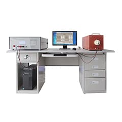
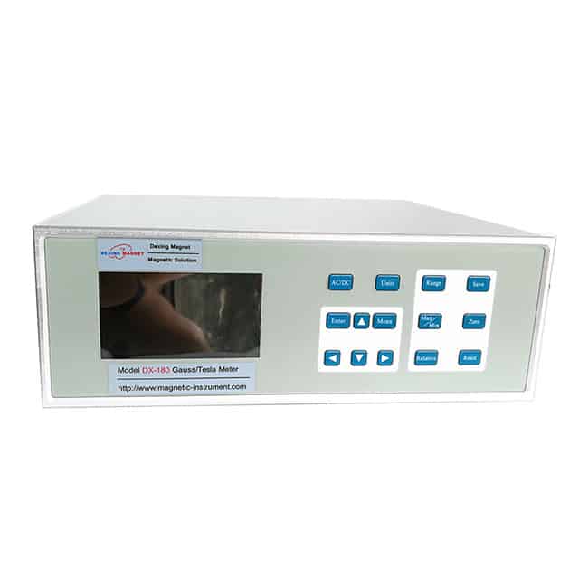
Test Instrument:
The Helmholtz instrument consists of two parts. They are the excitation coil frame part of the magnetic field measuring instrument part
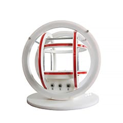
Helmholtz coil holder:
Two excitation coils: effective radius of the coil 105mm
The coil turns are 500
The center spacing of the two coils is 105mm
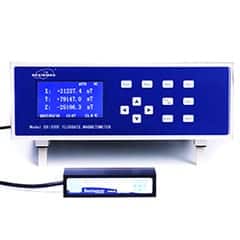
Measuring magnetic field sensor: 4501A uses Hall element to measure magnetic field.
Moving installation: transverse movable distance of 150mm, longitudinal movable distance of 50mm, distance resolution of 0.5mm
experiment content:
1. Measure the magnetic field distribution on the axis of the circular current coil
Connect the circuit. Adjust the output power of the magnetic field tester so that the effective value of the excitation current is I = 200mA. Take the center of the circular current coil as the coordinate origin and measure a UMAX value every 10.0mm. During the measurement, pay attention to keep the excitation current constant, record the data and draw the magnetic field distribution curve.
2. Measure the magnetic field distribution on the Helmholtz coil axis
Connect the two groups of coils of the magnetic field tester in series (pay attention not to reverse the polarity) and connect them to the output end button of the magnetic field tester. Adjust the output power of the magnetic field tester so that the effective value of the excitation current is still I = 200mA. The center point on the axes of the two circular coils is used as the coordinate origin, and the Umax value is measured every 10.0mm. Record the data and plot the distribution of the magnetic field.