
products categories

contact us
- If you have questions, please contact us, all questions will be answered
- Tel : 18030236818
- Fax : +86-592 5237901
- Email : dexing@china-dexing.com
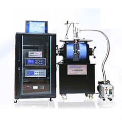

Hall Effect Measurement System
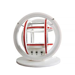
Helmholtz coil magnetic field measurement experiment
Helmholtz coils are two identical coils, parallel and coaxial to each other, the distance between the coils equal to the coil radius R. When the two coils are connected by current I in the same direction, the uniform magnetic field is generated in a large range on the coil axis (the line between the center of the two coils), and such coils are called Helmholtz coils.
一、The magnetic field of the current carrying circular coil
(a) shows the distribution of magnetic field intensity on the axis of a single liux-carrying coil; (b) shows the distribution of magnetic field intensity on the axis of two coaxial coils of the same coil.
二、Hall-effect sensor
The experiment requires high magnetic field measurement. Here Hall effect method is used to measure the magnetic field.
When the conductor with current I is placed in a magnetic field, an additional potential difference Eh will be generated in the direction perpendicular to current I and magnetic field B. This phenomenon was first discovered by Hall in 1879, so it is called Hall effect. The potential difference uH is called the Hall voltage.
As shown in the figure, under the action of Lorentz force F, the electrons of the conductor in the Hall effect deflected to the B side, which is located in the negative direction of the Y axis as indicated by the dotted arrow in the figure, and caused the accumulation of electrons on the B side and the accumulation of positive charges on the opposite side. At the same time, the moving electrons are also subjected to an opposing electric field force, f E, which is caused by the two accumulated dissimilar charges. With the increase of charge accumulation, f E increases. When the two forces are equal in magnitude (opposite in direction), f =-f E, then the accumulation of electrons will reach dynamic equilibrium.
Let's say the velocity of charge is V, F = bqV, so F =-f E
Bqv=Uq/l
U=Blv
Hall element current I= NQVLD
U = the IB/NQD - - - (a)
Hall coefficient Rh =1/ Nq
The magnitude of magnetic field B can be calculated from Equation (1) above.
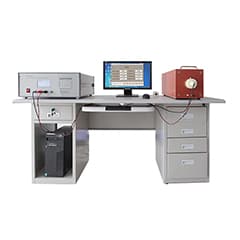
三、experimental instrument
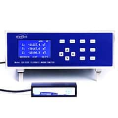
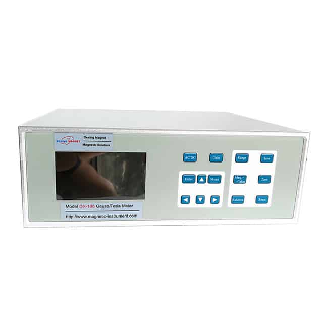
1. Milotesla meter
2. The ammeter
3. DC current source
4. Current regulating knob
5. Zero knob
6. Sensor plug
7. The fixed frame
8. Hall sensor
四、
Demonstrator
