
products categories

contact us
- If you have questions, please contact us, all questions will be answered
- Tel : 18030236818
- Fax : +86-592 5237901
- Email : dexing@china-dexing.com
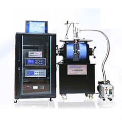
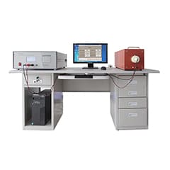
Hall Effect Measurement System
Three techniques help high-frequency Helmholtz coils generate strong magnetic fields
Many applications such as field induction, calibration, and scientific experiments often use high-frequency Helmholtz coils to generate uniform but time-varying high-frequency magnetic fields. Generating this magnetic field requires a high-frequency Helmholtz coil driver. Because the magnetic field density is proportional to the current, in order to generate a large magnetic field, you need to generate a large current. However, the coil impedance becomes high at high frequencies.
High frequency Helmholtz coil foundation
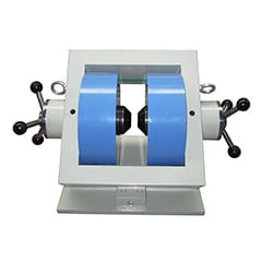
Helmholtz coils, named after the German physicist Hermann von Helmholtz, consist of two identical electromagnetic coils placed in parallel, centered on the same axis, like mirror images, as shown in Figure 1. When an electric current passes through the two high-frequency Helmholtz coils in the same direction, it creates a highly uniform magnetic field in three dimensions within the coils. These Helmholtz coils are often used to offset background (earth) magnetic fields, for measurement and calibration, and for magnetic fields in sensitivity tests of electronic equipment.
Design and manufacture of Helmholtz coils
The high frequency Helmholtz coil is made up of two coils. Because the two magnetic coils are designed to be identical, a uniform magnetic field can be generated when the radius of the coils equals the distance between them. The two coils are connected in series so that the same current is fed to them, creating two identical magnetic fields. Together, these two fields produce a uniform magnetic field in a cylindrical space at the center of two parallel coils.
The uniform magnetic field in this cylindrical space is approximately 25% of the coil radius (R) and the length is equal to 50% of the distance between the two coils. High frequency Helmholtz coils can be made with 1, 2, or 3 axes. The multiaxial magnetic coil can generate a magnetic field in any direction in the three dimensional space inside the Helmholtz coil pair. The most common high-frequency Helmholtz coil is circular. Square Helmholtz coils are also often used.
Helmholtz's magnetic field calculations
Each Helmholtz coil is made of a ring of electrical (copper) wire. When an electric current passes through it, a magnetic field is created. The magnetic field density is proportional to the current. The magnetic field formula of Helmholtz coil is as follows:

B= the magnetic field in teslas
N = number of turns of the coil
I= current in amperes
R = the radius of the coil in meters
A coil with a smaller radius produces a higher magnetic field density. The more turns in each coil, the stronger the magnetic field.
High frequency Helmholtz coil model
Helmholtz magnetic fields can be generated using either AC or DC. Most Helmholtz coil applications use a static (constant) magnetic field generated by a direct current. Some applications, such as scientific experiments, require high frequency non-static magnetic fields (kHz to MHz). This paper focuses on high frequency Helmholtz coils.
Each coil can be modeled as a parasitic resistor in series with an ideal inductor. The impedance of a parasitic resistor is generally very small. This model is sufficient for most high-frequency Helmholtz coil applications because the test frequency is much lower than the self-resonant frequency.
If the operating frequency of the Helmholtz coil is close enough to its self-resonant frequency, then the circuit model must also include its parasitic capacitors (CP1 and CP2). The parasitic capacitance is in parallel with each inductor resistor in series
The parasitic capacitor and inductor form a self resonant frequency. Although the coils are designed to match as much as possible, some minor differences between them are possible. Each coil has its own series resistance and parasitic capacitance. The parasitic capacitor and the coil inductor form a self-resonant frequency.
High frequency Helmholtz coil connection
High frequency Helmholtz coils may be in series (Fig. 2) or in parallel (Fig. 4). This series allows the current to flow through both magnetic coils to be exactly the same. In general, series can support the maximum current, which can generate the strongest magnetic field. However, since the two coils are in series, the total impedance is doubled. A higher impedance requires a higher driving amplifier voltage. Impedance can be reduced if the resonance technique described below is used.
Parallel Helmholtz coils have the advantage of lower impedance. In fact the impedance is reduced by half, but the current is also reduced by half (the current is divided into two parts), so the magnetic field is smaller. If the desired field density is achieved at half current and a low impedance is required, such as in low-voltage amplifier actuators, then parallel connection is acceptable
Drive high frequency Helmholtz coils
There are three ways to generate high frequency alternating magnetic fields. The first method is the direct drive method. This method is the simplest way to generate a test magnetic field. It easily changes the frequency and the magnetic field to be measured. The second method is series resonance. This is a great way to generate strong magnetic fields and magnetic fields with frequencies up to hundreds of kHz or even MHz. The third method is to use a new electrically driven large resonance method. This method produces the highest magnetic field density. Each method is described in detail below.
Direct drive method
If the experiment is low frequency, or the coil is low inductance, or both, the Helmholtz coil can be driven directly with a waveform amplifier driver (such as Accel Instruments' TS250 waveform amplifier). Because of low frequency or low inductance, the coil impedance is low enough to be driven directly by the amplifier