
products categories

contact us
- If you have questions, please contact us, all questions will be answered
- Tel : 18030236818
- Fax : +86-592 5237901
- Email : dexing@china-dexing.com
Hall Effect Measurement System
The basic principle of vibrating sample magnetometer (VSM) is analyzed
What is VSM?
Vibrating Sample Magnetometer (VSM) is one of the important means for measuring magnetic properties of such materials, such as ferromagnetic, subferromagnetic, antiferromagnetic, paramagnetic and diamagnetic materials
It includes magnetic studies of rare earth permanent magnet materials, ferrite materials, amorphous and quasicrystalline materials, superconducting materials, alloys, compounds and biological proteins, etc.
VSM can be used to detect the intrinsic magnetic properties of various materials, such as magnetization Ms (σ S), Curie temperature Tf, coercivity mHc, remanence Mr, etc. After predicting the demagnetization factor N of the sample in the measurement direction
Other technical magnetic parameters, such as Bs, BHc, (BH) Max, are obtained. In addition, magnetic properties of tested samples can be judged according to the characteristics of loop.
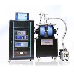
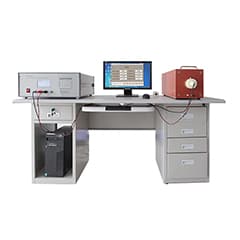
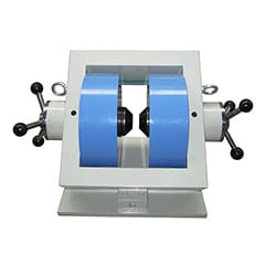
Instrument structure
Vibrating sample magnetometer is mainly composed of electromagnet system, sample forced vibration system and signal detection system.
Detection principle
When the power output of the oscillator is fed to the vibration head drive coil, the vibration head can make the vibration rod fixed on the drive coil drive constant amplitude vibration with the frequency of ω, so as to drive the sample tested in the magnetization field H for the same vibration; In this way, the dipole field generated by the magnetized sample in space will vibrate the same with respect to the stationary detection coil, resulting in the induction voltage of ω frequency generated in the detection coil; The voltage output of the oscillator is fed back to the PLL amplifier as a reference signal. After the induction voltage with the above frequency of ω is fed to the normal working condition of the phase-locked amplifier (the so-called normal working, that is, the measured signal of the phase-locked amplifier is the same frequency and phase as its reference signal), a DC voltage V J out, which is proportional to the total magnetic moment of the tested sample, is output through amplification and phase detection. Corresponding to this, there is a dc voltage V H out proportional to the magnetization field H (that is, the voltage on the sampling resistance or the output voltage of the gauster), the corresponding voltage diagram of the two, can get the hysteresis loop of the tested sample (or magnetization curve).
Many intrinsic magnetic properties of the tested sample can be obtained by predicting the volume, mass, density and other physical quantities of the tested sample. If the demagnetization factor N of the sample can be known, not only can the magnetic induction and technical hysteresis (magnetization) curves of the internal magnetization field H I of the material (material) be obtained from the above measured curves, but also many technical magnetic parameters such as B r, H C, (BH) Max can be obtained from the above measured curves.
For simplicity, let's take a rectangular coordinate system, as shown here. It is assumed that the sample S is located at the origin and vibrates simply along the Z direction, a=a 0 cosωt, a 0 is the amplitude and ω is the vibration frequency. The magnetization field H is applied along the direction, and it is assumed that a detection coil with the number of turns N and its axis in the Z direction is placed at a distance r from S, and the cross-sectional area of its NTH turn is S N (note: S N ≠ s m, that is, the cross-sectional area of any two turns is unequal). If the geometric scale of sample S is very small compared with r, that is, sample S can be regarded as a magnetic dipole from the space where the detection coil is located.
Sample preparation
One of the advantages of VSM open-circuit measurement is that there are no strict requirements on the shape of the sample. The sample only needs to be cut into small particles with a diameter of about 2-3mm before measurement.
Block material: for strong magnetic materials, remove about a few milligrams of small pieces from the bulk material in an appropriate manner (but do not use iron tools to obtain, so as to avoid the sample is contaminated by strong magnetic), its size can be put into the sample holder.
Powder: for strong magnetic materials such as ferrite before the sintering process of powder, with a precise balance weighing about a few milligrams (small magnetic moment can be appropriately weighed out some). With soft paper tightly wrapped into a small ball (such as: with 1/4 pieces of brush mirror paper folded into the balance to weigh its quality, and then use a spoon to take powder carefully placed in the folding Angle of the paper - the paper is larger and more porous, so it needs to fold into a double layer, read the total mass number, the sample of the single mass is before and after weighing the difference). Note: when wrapping, make sure that the powder is concentrated in a small area as far as possible.
Demagnetization field correction
The so-called "demagnetizing field" means that when the sample is magnetized, its M will produce "magnetic charge" at both ends of the sample, and this "magnetic charge pair" will be generated in the magnetic field in the opposite direction of the magnetization field, thus weakening the magnetization of the external magnetization field H, so it is called demagnetizing field.
The demagnetization field can be expressed as Hd= -nm, and N is called the "demagnetization factor". Depending on the shape of the sample, it is generally very complicated, even in the form of a tensor. Only by rotating the ellipsoid can the specific values of the three directions be calculated. In the property measurement, the samples are usually made into several degenerate types of rotary ellipsoid: spherical, thin line and thin film. At this time, the N of the specific direction of these samples is a constant value, such as 1/3 when spherical, N=0 along the axis of the thin line, N=0 along the membrane surface, etc. When the volume V of the sample or its mass m is known, the magnetization of the sample m =J/ V or mass magnetization σ=J/m can be obtained. If the demagnetization factor N in the direction H of the magnetization field can be predicted, the corresponding relationship between M(σ) and Hi can be made into a curve when the internal magnetization field Hi = h-nm. The modified magnetization curve or hysteresis loop M ~ H or σ ~ H of the tested sample can be obtained.