
products categories

contact us
- If you have questions, please contact us, all questions will be answered
- Tel : 18030236818
- Fax : +86-592 5237901
- Email : dexing@china-dexing.com
Hall Effect Measurement System
The basic principle of vibrating sample magnetometer (VSM) is analyzed
01 What is the VSM?
Vibrating Sample Magnetometer, Vibrating Sample VSM is one of the important means to measure the magnetic properties of materials. It is widely used in the magnetic properties of various ferromagnetic, ferromagnetic, antiferromagnetic, paramagnetic and diamagnetic materials, including rare earth permanent magnet materials, ferrite materials, amorphous and quasicrystal materials, superconducting materials, alloys, compounds and biological proteins, etc.
VSM can be used to detect the intrinsic magnetic properties of various materials, such as magnetization Ms (σ S), Curie temperature Tf, coercivity mHc, remanence Mr, etc. Other technical magnetic parameters, such as Bs, BHc, (BH) Max, can be obtained indirectly by predicting the demagnetization factor N of the sample in the direction of measurement. In addition, magnetic properties of tested samples can be judged according to the characteristics of loop.
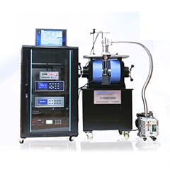
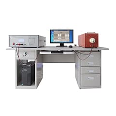
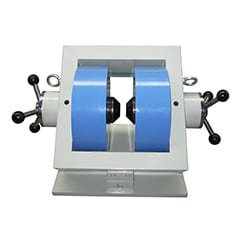
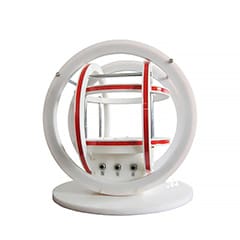
02 Instrument Structure
Vibrating sample magnetometer is mainly composed of electromagnet system, sample forced vibration system and signal detection system.
03 Detection Principles
When the power output of the oscillator is fed to the vibration head drive coil, the vibration head can make the vibration rod fixed on the drive coil drive constant amplitude vibration with the frequency of ω, so as to drive the sample tested in the magnetization field H for the same vibration; In this way, the dipole field generated by the magnetized sample in space will vibrate the same with respect to the stationary detection coil, resulting in the induction voltage of ω frequency generated in the detection coil; The voltage output of the oscillator is fed back to the PLL amplifier as a reference signal. After the induction voltage with the above frequency of ω is fed to the normal working condition of the phase-locked amplifier (the so-called normal working, that is, the measured signal of the phase-locked amplifier is the same frequency and phase as its reference signal), a DC voltage V J out, which is proportional to the total magnetic moment of the tested sample, is output through amplification and phase detection. Corresponding to this, there is a DC voltage V H out proportional to the magnetization field H (that is, the voltage on the sampling resistance or the output voltage of the Gauss meter), the corresponding voltage diagram of the two, can get the hysteresis loop (or magnetization curve) of the tested sample.
Many intrinsic magnetic properties of the tested sample can be obtained by predicting the volume, mass, density and other physical quantities of the tested sample. If the demagnetization factor N of the sample is known, not only the magnetic induction B and the technical hysteresis (magnetization) curve of the internal magnetization field H I of the material (material) can be obtained from the above measured curve, but also many technical magnetic parameters such as B r, H C, (BH) Max can be obtained from the above measured curve.
For simplicity, let's take a rectangular coordinate system, as shown here. It is assumed that the sample S is located at the origin and vibrates simply along the Z direction, a=a 0 cosωt, a 0 is the amplitude and ω is the vibration frequency. The magnetization field H is applied along the direction, and it is assumed that a detection coil with the number of turns N and its axis in the Z direction is placed at a distance r from S, and the cross-sectional area of its NTH turn is S N (note: S N ≠ s m, that is, the cross-sectional area of any two turns is unequal). If the geometric scale of sample S is very small compared with r, that is, sample S can be regarded as a magnetic dipole from the space where the detection coil is located